X-Max V3 Pro Plus Tech Dump
I recently purchased a X-Max V3 Pro Plus vaporizer, and I was hoping I could hack it to display a different boot logo, just for fun.
In the end, I didn't achieve my goal - but I did break it open and found some details about the device that I couldn't find elsewhere, so this is an article that contains a dump of the information I gathered.
Hardware
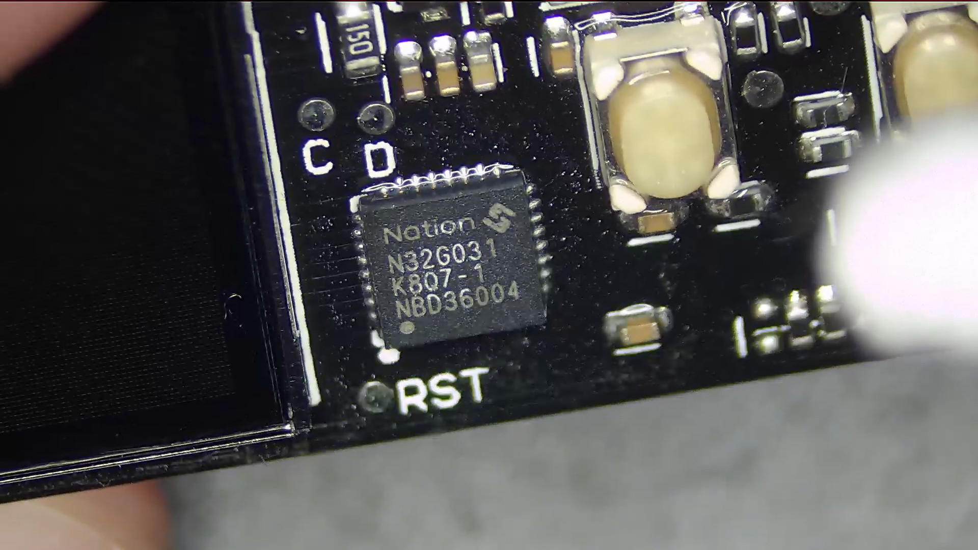
The main MCU is a N32G031K8Q7-1. It is a Nations Technologies Inc. N32G031 series controller based on an ARM Cortex-M0 with 64KB embedded flash, 8KB SRAM in a QFN32 (4x4mm) package.
Pinout
The populated side of the PCB has some annotated pads that are also routed to the other side of the PCB. The RST corresponds to R pad on the backside.
Pinout (backside)
I tried connecting to the pads on the back as they were a bit easier to get to:
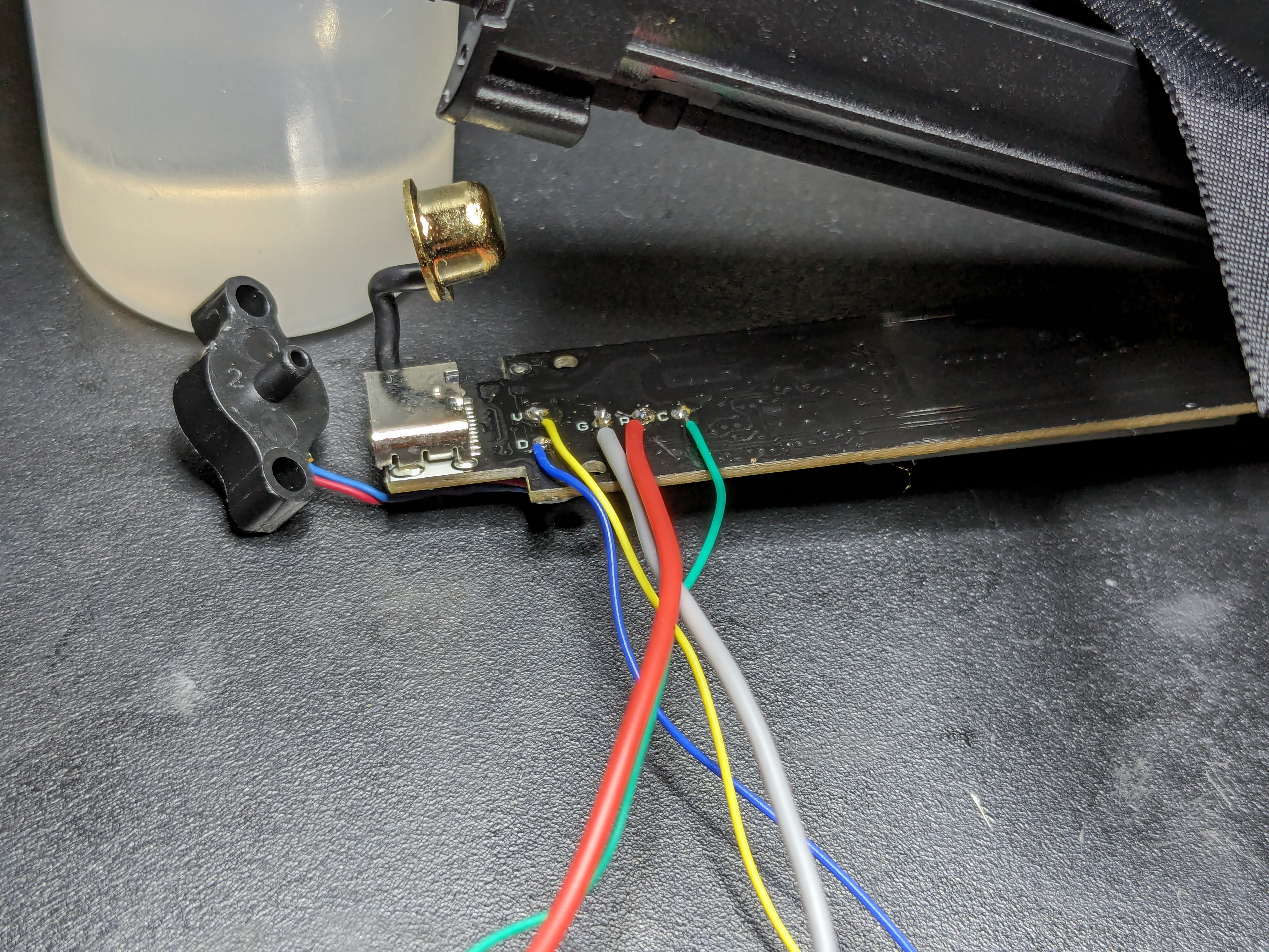
There are 5 pads - V, D, G, R, C.
This is what I traced them to:
| Annotation | Pin # | Function |
|---|---|---|
| V | - | BAT+ |
| D | 23 | PA23 (SWDIO) |
| G | - | BAT- |
| C | 24 | PA14 (SWCLK) |
| R | 4 | nRST (Reset) |
Programming
SWD
I tried to connect a SEGGER J-Link via SWD, but it wouldn't connect:
J-Link>connect
Device "N32G031C8" selected.
Connecting to target via SWD
Failed to attach to CPU. Trying connect under reset.
Error occurred: Could not connect to the target device.
SWD may be disabled in the production units.
I wanted to try and pull the BOOT0 pin high to put in in system memory mode, but I couldn't find an exposed pad for it, and I didn't have a soldering tip small enough to solder directly to the QFN chip.
Notes
Unfortunately I didn't take any top-down pictures of the board, but I've uploaded the uncut (sorry) video capture from my microscope if you want to take a look.
The video can be found here.